
Identifying Transformers
Identifying Salvaged Transformers
Every experimenter accumulates various and sundry audio output transformers-the type that’s used to match a power tube, or tubes, to a loudspeaker. He salvages them from old radio receivers with an idea that one day they’ll be useful. Sooner or later our hero finds that he has neglected to tag or otherwise identify the transformer he has stowed away. The equipment needed to identify a transformer consists of; an a.c. vacuum tube voltmeter, such as the Heathkit Model AV-2; a small 6.3-volt filament transformer, such as the Triad F-13X (any 1-ampere unit will do as well); a 10,000-ohm wire-wound potentiometer; and a power cord and plug. 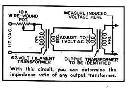 Set up the circuit shown in the schematic diagram. If you are unable to tell by inspection which two of the four or five leads coming out of your transformer are the secondary connections, measure the d.c. resistances between the various leads. The two leads (of a 4- or 5- lead output transformer) that have the lowest resistance are the secondary leads. If you’re checking a 4-lead transformer, the two remaining leads are the primary. If you’re checking a 5-lead transformer, the two remaining leads that have the highest resistance are the two plate leads; the third lead is the center-tap connection. A 4-lead output transformer is made to match a single tube to a speaker voice coil. A 5-lead transformer matches push-pull tubes to the voice coil. After you’ve made the few simple connections, set the potentiometer to where the full 10,000 ohms is in the circuit, and plug the line cord into the 117-volt a.c. socket. Connect your v.t.v.m. across the secondary of the output transformer. Then, adjust the potentiometer until your meter reads exactly 1 volt. As soon as this adjustment has been made, set your meter to a higher range (the 100-volt range will usually be the right one), and immediately switch the meter leads to the primary of the output transformer. Measure the voltage across the primary and write it down. Multiply this number by itself, and then multiply the product by the voice-coil impedance of the speaker you want to use. Your final figure is the load impedance into which the plate of your power tube will work when you’re using this particular transformer and speaker.
HOW IT WORKSIt is easy to identify the impedance ratio of an output transformer by means of two useful iron-core transformer formulas: (Ns/Np)2 = Zs/Zp and Ns/Np = Es/EpIn which Ns represents the number of turns on the secondary of our output transformer, Np the number of turns on the primary, Zs the impedance to be placed across the secondary, Zp the impedance reflected into the primary, Es a voltage impressed or induced across the secondary, and Ep the voltage impressed or induced across the primary. |
In this circuit, a filament transformer is used to drive the secondary of the unknown transformer. The voltage is carefully adjusted and measured by an a.c. vacuum tube voltmeter. Once the secondary voltage is known, the v.t.v.m. is used to measure the voltage induced in the primary. Through the formula above, the nominal primary load impedance can be found.
EXAMPLE I: Suppose, after the setting the voltage across the secondary of our output transformer very carefully to 1 volt, we read the voltage across the primary and find it to be exactly 39.5 volts. We write this down and multiply it by itself (39.5 X 39.5) and obtain the product: 1560.25. The voice-coil impedance of the speaker we want to use happens to be 3.2 ohms, so we multiply our 1560.25 by 3.2 and get 4992.8. This is close to 5000, so we’ll call it 5000 ohms – the right impedance to match the plate of a 6V6 or a 6AQ5 power tube.
EXAMPLE II: Suppose we have a 5-lead output transformer and, after carefully setting its secondary to 1 volt, we measure the voltage across the two primary plate leads and find it to be 42 volts. We have an 8-ohm speaker, so we multiply 42 X 42 X 8 and get 14,112. Call it 14,000 ohms. This will match a pair of 6F6’s, or 6K6GT’s, or 6AR5’s in push-pull to the voice-coil of our 8-ohm speaker.
Proper plate loads at various grid bias and plate potentials for a number of power tubes can be found in the RCA Receiving Tube Manual, or the tube section of The Radio Amateur’s Handbook published by the American Radio Relay League (A.R.R.L).
– Frank H. Tooker
This ‘system’ is very similar to other ideas presented in books such as The Groove Tube Book 4. Regardless of which method you employ, please don’t put faith in the 100% accuracy of your measurement or final impedance calculation. For starters, the impedance ‘reading’ will be only accurate at 60Hz. Secondly, as the article states… ‘This is close to 5000, so we’ll call it 5000-ohms…’. You aren’t interested in the exact value, down to the single ohm, anyway. You want to determine the suitability of any ‘unknown’ transformer you have to the application you desire. The rest is then up to your eyes and experience to rationalize if the calculated impedance is ‘in the ballpark’ for a specific tube type, and if the transformer can handle the power and current tasks you may ask of it. Should the 10K potentiometer not provide enough ‘range’ (as sometimes happens to my own unit) you can add a series resistor to the input of the potentiometer. I also decided to try a 6.8K/5-watt resistor (that I had handy) in series with a 5K wire-wound pot. I now had all of the range I would need, plus a ‘smaller’ potentiometer where I can easily get a very quick and accurate 1VAC setting. Other ‘mods’ I did to the basic design was to include;
- an on/off switch
- a neon pilot light (before the resistor/pot)
- 2 pairs of clip leads to attach to the transformer under test and a DMM.
*WARNING*
Please make sure you use a wire-wound pot!
The whole project took me about an hour and a half to complete at a cost of less than $30. Below is a chart with some sample readings I obtained. Remember, you aren’t trying to match my readings +1%. These are guidelines only.
 |
||||
< p style=”text-align: left;”>Lastly, please read over and over again the sentence… “Proper plate loads at various grid bias and plate potentials for a number of power tubes can be found in the RCA Receiving Tube Manual.” I’ve said it at least a dozen times; biasing by the current draw method is only any good if you are 100% familiar with the tube, the output transformer, and the amplifier in question. Otherwise, be cognizant of the fact that plate resistance changes with plate voltage and/or bias voltage. I’m sure I’ve said that at least a few times as well.